

1.1 Rotor Assembly
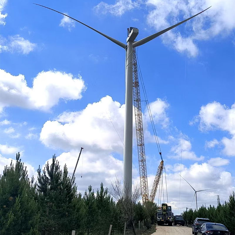
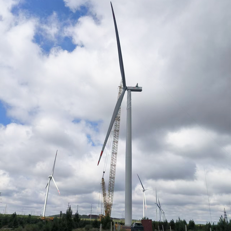
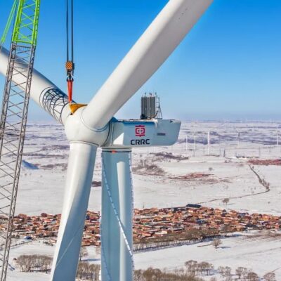
The WT6250D175 european wind turbine rotor system is composed of 3 blades, pitch system and w hub. The blade is connected to the inner ring of pitch bearing by bolts, and the outer ring of pitch bearing is connected to the hub.
Rotor speed is regulated by a combination of blade pitch angle adjustment and generator/converter torque control. The rotor spins in a clockwise direction under normal operating conditions when viewed from an upwind location.
Full blade pitch angle range is approximately 90 degrees, with zero degree position being with blade flat to the prevailing wind. Pitching the blades to a full feather pitch angle of approximately 90 degrees accomplishes aerodynamic braking of the rotor, thus reduces the rotor speed.
The pitch system adopts electric gear to adjust and maintain blade pitch Angle. The variable pitch bearing transfers the blade load to the european wind turbine hub, which drives the spindle rotation to the gearbox generator, which generates electrical energy.
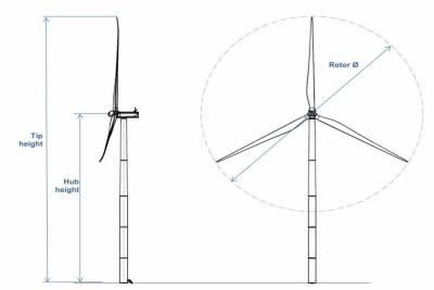
2.1 6.25MW European Wind Turbine Specification
This table shows the major parameters of eu wind turbine.
Technical Characteristics for WT6250D175 wind power europe
|
Parameter |
Unit |
Parameter |
|
Rated Power Design Lifetime Design WTG Class |
kW — — |
6250 25 IEC S |
|
Vref |
m/s |
42.5 |
|
Vave |
m/s |
7.5 |
|
Rated wind Speed |
m/s |
11.1 |
|
Iref |
— |
0.15 |
|
Number of Blades |
— |
3 |
|
Rotor Coning/Shaft Tilt |
° |
6/8 |
|
Rotor Diameter |
m |
175 |
|
Standard Operational Temperature Range |
˚C |
-30˚C ~ 45˚C |
|
Survival Temperature Ranges |
˚C |
-40˚C ~ 50˚C |
|
Hub Height |
m |
105-160(can be customized) |
|
Wind Speed Cut-In |
m/s |
3.0 |
|
Wind Speed Cut-Out |
m/s |
25 (soft cut out) |
|
Blade Length |
m |
86 |
|
Blade Material |
— |
GFRP (glass fiber reinforced Polyester) |
|
Pitch System |
— |
Electrical system |
|
Yaw System |
— |
Plain Bearing with externally geared ring |
|
Generator Type |
— |
Doubly Fed Induction Generator |
|
Number of Generator Pole Pairs |
— |
4 |
|
Rated Frequency |
Hz |
50 |
|
Rated Power Factor |
— |
-0.95 to 0.95 (can be customized) |
|
Generator Rated Voltage |
V |
1140 |
|
Rated Generator Speed |
rpm |
1720 |
3 Eu Wind Power Mechanical Design
3.1 Wind Energy Rotor
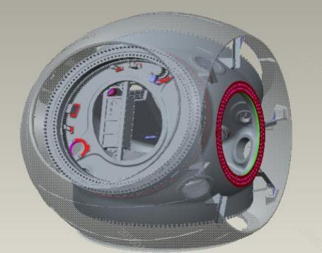
The european wind turbine is equipped with a rotor consisting of three blades and a hub. The hub is a ball shell shape of cast iron material. Each blade is equipped with a set of electrical pitch systems and a super capacitor power backup system. Based on the prevailing wind conditions, the blades are continuously positioned to optimize the power output.
Rotor Parameters
|
Parameter |
Unit |
Value |
|
Diameter |
m |
175 |
|
Swept Area |
m2 |
24030.6 |
|
Rated Rotating Speed |
rpm |
8.6 |
|
Coning/Shaft Tilt |
° |
6/8 |
|
Tip Speed |
m/s |
78.8 |
3.2 Wind Turbine Blade
The WT6250D175 european wind turbine blade consists of two structural shells bonded together along with internal shear webs that provide further stiffness to the structure. The blade is designed to resist extreme and fatigue loads, to be aeroelastic stable, and combing with turbine configuration, to restrict tip deflections to elude tower collisions and avoid resonances.
Blade Parameters
|
Parameter |
Unit |
Value |
|
Blade Length |
m |
86 |
|
Material |
— |
Glass fiber reinforced Polyester |
3.3 Eu Wind Power Pitch system
The pitch system incorporates an electric pitch mechanism and a pitch control system. It utilizes 3 AC permanent magnet motors with multi-stage planetary drive units and 3 independent sets of super-capacitors installed on each blade axis. Control signals and power to the pitch system are managed through slip rings on the back of the gearbox.
The pitch drive system comprises components including pitch motors, gearbox, and bearings. It executes blade rotation according to the main controller's commands and control strategies, regulating the energy from incoming wind acting on the turbine. The pitch adjustment mechanism can also initiate turbine shutdown by rotating blades into neutral position. Each blade requires three independent pitch actuators for synchronized operation. As blade failure scenarios are detailed in the load calculation section, redundant design considerations must be implemented during system design to prevent extreme failures such as simultaneous blade malfunctions across all three blades.
Pitch System Parameter
|
Parameter |
Unit |
Parameter |
|
Maximum pitch speed |
deg/s |
4 |
|
Pitch Angle Range |
deg |
0~90 |
|
Pitch Bearing |
— |
Tri-roller Bearing |
3.4 Drivetrain
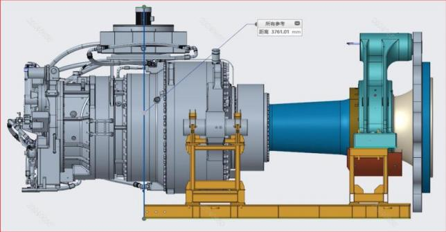
The Drivetrain system mainly includes the main shaft system, one main bearing, main gearbox with torque arms and generator etc. The effective torque is transmitted for energy conversion. The non-effective load such as the bending moment and thrust of the rotor is transmitted to main frame, and high-speed output shaft braking and rotor locking functions are provided for the maintenance of wind turbine rotor and drivetrain.
3.4.1 Main shaft
The main shaft is connected to the hub with bolts to transfer the rotational energy of wind rotor to the gearbox.
Main shaft parameter
|
Parameter |
Unit |
Value |
|
Shaft Material |
— |
Forged |
3.4.2 Main bearing
The main bearing is supporting the main shaft assembly. The main bearing and torque arms on the gearbox form three-point support structure. The main bearing is double-row spherical roller bearing. Its inner race is connected to the main shaft, while its outer race fits with the main bearing housing.
Main Bearing Parameter
|
Parameter |
Unit |
Value |
|
Bearing Type |
— |
Double Row Spherical Roller Bearing |
3.4.3 Eu Wind Power Gearbox
As the key component of drivetrain wind turbine system, gearbox is connected with shaft at front end, and connected with the coupling of high-speed shaft and generator at rear end, so as to transmit the torque. The torque arm of eu wind power gearbox is fixedly connected with the main frame through elastic support. The gearbox has 3 planetary stages and 1 parallel stage.
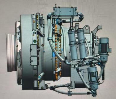
Gearbox parameter
|
Parameter |
Unit |
Value |
|
Ratio |
— |
195.35 |
|
Number of gear stages |
— |
3P1H |
|
Gear oil cooling |
mm |
Water Cooling |
|
Main shaft-gearbox connection |
— |
Expanding ring |
|
Gearbox-generator connection |
— |
Flexible coupling |
3.5 Yaw system
The yaw system is designed to control the nacelle orientation relative to the wind direction while securing the nacelle to the top of the tower. Several electrical yaw motors, actively controlled by the european wind turbine control system, are used to adjust the nacelle position relative to the tower when the rotor orientation is not pointed into the wind within an allowable time-averaged tolerance. The rotation of each of the yaw motors is transferred through a yaw drive gearbox to a pinion which engages with the plain bearing gear that is mounted on the tower.
Yaw system parameter
|
Parameter |
Unit |
Value |
|
Yaw Drive |
— |
Externally Electrically Drive |
|
Yaw Bearing Type |
— |
Plain Bearing |
|
Brake Type |
— |
Pretensioned Spring |
|
Number of Yaw Drive Motors |
— |
18 |
|
Number of Yaw Brakes |
— |
13 |
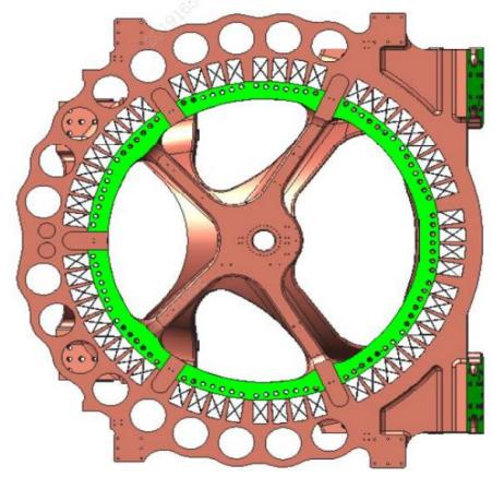
3.6 Bedplate and Rear Frame
The Bedplate mainly supports the transmission chain and yaw components, and bears the load transmitted by the bearing and gearbox housing, positioning the yaw gear ring, yaw drive and yaw brake system, bearing the rotor lock load. the rear frame is mainly used to support the generator and other components.
Bedplate and Rear Frame
|
Parameter |
Unit |
Value |
|
Type of bedplate |
- |
Casting |
|
Rear Frame |
- |
Welded Structure |
3.7 Nacelle
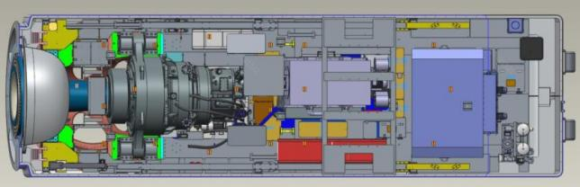
The modularized nacelle canopy house the whole nacelle and the components inside. On the front is the drive train system. The generator is located at the rear right side and the convertor is at the rear left side. The transformer is located at the rear side. One water pump station sits at the very rear left side of the nacelle and it circulates the water to the cooler on nacelle roof top for cooling the gearbox, generator, transformer and convertor.
4 Electrical design
4.1 European Wind Turbine Generator
The WTG european wind turbine is a DFIG type with 4 pairs of poles. The generator is for horizontal installation and equipped with water cooling system.
Generator Specifications
|
Parameter |
Unit |
Value |
|
Rated Power |
kW |
6400 |
|
Type |
— |
Doubly Fed Induction Generator |
|
Number of Poles |
- |
4 |
|
Cooling method |
— |
water cooling |
|
Rated Voltage |
V |
1140 |
|
Rated Output Speed |
rpm |
1720 |
|
Rated frequency of generator |
Hz |
50 |
4.2 European Wind Turbine Converter
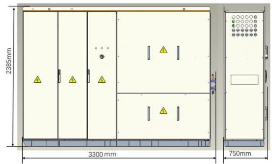
The converter system consists of an LV distribution circuit, complete converter power, control and distribution protection circuits. The rotor-side converter in the converter is connected to the rotor side of doubly fed generator while the gird-side connected to the grid. The rotor-side converter controls the generator torque and the reactive power exchanged between the stator side and the power grid by generating three-phase voltages with different amplitudes and frequencies. The gird-side converter exchanges active power with the power grid. The amplitude of such active power is the active power absorbed or emitted by the rotor-side converter.
The partial power converter is used which means that the power electronic system of converter is approximately 30% of the capacity of the DFIG. However, the full power goes through whole converter system, which includes power electronic system and electrical system such as main circuit breaker, stator contactor, is equal to the rated power of the WTG.
The converter system consists of a converter on the rotor side, a DC intermediate circuit, and a power inverter on the grid side. The converter system consists of a power module and the associated electrical equipment.
Converter Specifications
|
Parameter |
Unit |
Value |
|
Cooling method |
— |
water cooling |
|
Capacity |
— |
Approximately 30% of WTG rated power |
|
Rated frequency of generator |
Hz |
50 |
4.3 Transformer
The 6.25MW european wind turbine is connected to the grid of wind farm via step-up transformer. The transformer is a three-phase, three limb, two-winding, dry type and located in the rear side of the nacelle. The rated voltage of HV-side of step up transformer is normally 35kV, and the transformer is capable of no-load voltage regulation. The LV-side voltage of step-up transformers is 1140V.
4.4 High Voltage Switchgear
A high voltage switchgear is installed in the bottom of the tower as an integrated part of wind turbine. The condition of the switchgear and high voltage safety related devices in the turbine are being monitored by the wind turbine control system. If the circuit breaker is tripped due to a fault detection, the circuit breaker will only be re-connected manually. The switchgear has three variables depending on how many grid cables go into the independent wind turbine.
5 Grid Performance Specification 50Hz
This 6.25MW european wind turbine has the capability of primary frequency regulation, the ability to control active and reactive power quickly, precisely and over a wide range, and the ability to output excellent power quality.
This WTG european wind energy also has the capability to ride through low and high voltage faults, inertia response and primary frequency regulation, the ability to control active and reactive power quickly, precisely and over a wide range, and the ability to output excellent power quality. They can automatically detect the sub-synchronous and super-synchronous oscillation states of the units and provide oscillation suppression strategies.
6 Safety System
6.1 Lightning system
The Lightning Protection System (LPS) helps protect the wind turbine against the physical damage caused by lightning strikes. The LPS consists of several parts:
- Lightning receptors anddownconducting cables in/on the blade
- Protection againstovervoltageand overcurrent
- Shielding againstmagnetic andelectrical fields
- Earthing system
6.2 Access
Access to 6.25mw european wind turbine from outside is through a door located at the entrance platform approximately 3-4 meters above ground level. The door is equipped with a lock. Through service lift inside the tower or ladder one can access to the top of the wind turbine. Fall arrest equipment is needed. From the top tower there is a ladder about 10m from the nacelle.
The nacelle consists of the main nacelle house which hosts the drivetrain. There are walkways along either side of the drivetrain and at the rear end of the nacelle main house.
After the 6.25MW european wind turbine generator is carefully stopped and locked according to the requirement, from under the drivetrain, through a hatch one can enter the hub. Via the ladder in the nacelle, one can go out to the nacelle top.
6.3 HSE
The 6.25MW european wind turbine is designed according to the requirements in EN50308 to address all possible occupational health hazards and safety hazards, to keep personnel healthy and safe.
- Guarantee safe working space that conforms to safety standards, including platforms, guardrails, safety channels, and design against electric shock to prevent accident occurrence.
- Provide safety warning signs to remind the operation personnel of any potential danger.
- Anchor points for the personnel workingatheight.
- Emergency escape system to guideevacuationfor emergencies.
- Provide environmental protection requirements, including hazardous waste handling, energy conservation, and environmental protection.
- Provide requirements for limits of hazardous factors such as noise and radiation that comply with the occupational health requirements.
- All floors have anti-slip surfaces. There is onefloor per tower section.